A dual purpose blog, firstly aimed at junior and intermediate games programmers with some tutorials I've put together to pass on some bits of knowledge from my time at Uni and beyond. And second to document and present my progress in indie games development.
HLSL Tutorial 1: An Introduction to HLSL
This tutorial is intended to give an explanatory introduction to the concepts and basic usage of HLSL.
Higher Level Shader Language, or HLSL, is a C based programming language designed to be executed on graphics devices in the form of an effect file (.fx). These effect files are essentially a list of instructions for the graphics device to use to render pixels to the screen frame buffer or to separate render targets (more on these later).
An effect file or 'shader' as their commonly known is broken down into four parts:
1) Global variables (from your program &/or internally defined globals).
2) Input & Output 'struct's containing data to be input or output from shader methods.
3) The shader methods themselves, which must contain a 'Vertex Shader' and 'Pixel Shader' function for 3D rendering.
4) The techniques section, which contains combinations of vertex and pixel shader function pairs and essentially provides a way of having multiple shading techniques within one file.
Lets take a closer look, below is a breakdown of the most simplest 3D shader file I can think of, its also the default effect file created inside the XNA game studio environment.
1) The Global Variables:
float4x4 World;
float4x4 View;
float4x4 Projection;
Note the syntax here, a float4x4 is the same as defining a 'Matrix' in XNA. So here you have a world, view and projection matrix. Each of these needs to be properly assigned for the shader to function correctly. Note parameters that are not assigned or updated correctly will produce incorrect results.
2) Input & Output structs:
struct VertexShaderInput
{
float4 Position : POSITION0;
};
struct VertexShaderOutput
{
float4 Position : POSITION0;
};
Here there are two structs, one representing data going into the vertex shader, and another for the data coming out of the vertex shader. Its possible to have multiple structs for different vertex and pixel shaders or even just for helper methods or internal objects but don't worry too much about that for now.
the 'float4 Position : POSITION0;' line defines a float4 (like a Vector4, float3 for Vector3 etc) to represent a position vector. The colon you may recognise from C# to donate inheritance and a similar thing is happening here. What this line is saying is 'I have a float4 called position, and it either takes its value from, or assigns it to, register 'POSITION0'. There are several register types and some have multiple slots, e.g. TEXCOORD0, TEXCOORD1, TEXCOORD2 etc. More on these later.
3) Vertex & Pixel Shader functions:
VertexShaderOutput VertexShaderFunction(VertexShaderInput input)
{
VertexShaderOutput output;
float4 worldPosition = mul(input.Position, World);
float4 viewPosition = mul(worldPosition, View);
output.Position = mul(viewPosition, Projection);
return output;
}
float4 PixelShaderFunction(VertexShaderOutput input) : COLOR0
{
return float4(1, 0, 0, 1);
}
Here you can see the input & output structs at work, serving as easy ways of inputting and outputting data between functions. Note that the pixel shader takes the vertex shader output struct as its input, and only returns a colour value. This is because in the end all we are calculating is a pixel colour value. In this case there is no calculation, we simply colour the pixel red, the float4 is formatted here similar to the XNA 'Color' data type, with rgba values.
The Vertex shader is the only one of the two functions actually doing any calculation, using the input struct data and the global variables defined at the top of the file (1). The vertex shader has to translate the vertex from model space to projection space, which takes a few steps:
1) Multiply (mul) the input struct position vector by the world matrix, transforming it to the position you want it in your game.
2) Multiply the new world position by the view matrix, transforming the position around the view direction of the camera so you see the surface of the model facing the camera.
3) Multiply the view space position by the projection matrix, transforming the position to fit the aspect ratio and viewing frustum set up in your game, this also culls vertices outside the bounds of the near and far clipping plane (essentially ignoring vertices that are too close or too far away to bother with).
4) The techniques section:
technique Technique1
{
pass Pass1
{
VertexShader = compile vs_2_0 VertexShaderFunction();
PixelShader = compile ps_2_0 PixelShaderFunction();
}
}
There is only one 'technique' defined here as 'Technique1', with only one 'pass' defined as 'Pass1'. A technique can have multiple passes for complex rendering techniques but don't worry about that for now. Each pass must have VertexShader and PixelShader (though 2D effects require only a Pixel Shader). The shader functions are assigned by instructing the device to compile your specified functions using the vertex shader and pixel shader libraries (vs_2_0 is VertexShader 2.0, ps_2_0 is PixelShader 2.0 etc).
When rendering multiple models you may want different effects for different models, such as height mapped terrain, a water shader etc. Techniques offer a way of having multiple shading techniques in one effect file, as you can specify in game code which technique to use for each model.
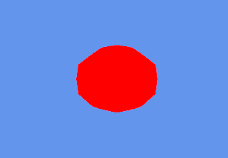
For those who are curious, this rather skinny shader produces this rather un-3D looking result:
The reason this looks so dull is because there is no lighting at work, every pixel is the exact same colour red, so we get no perception of this being a 3D sphere.
I hope this article was useful, check out other tutorials to see how to develop more advanced effects and how to integrate shaders into XNA.
Subscribe to:
Comments (Atom)

No comments:
Post a Comment